1.2. The OpenGL Pipeline
1.2.1. The deprecated model
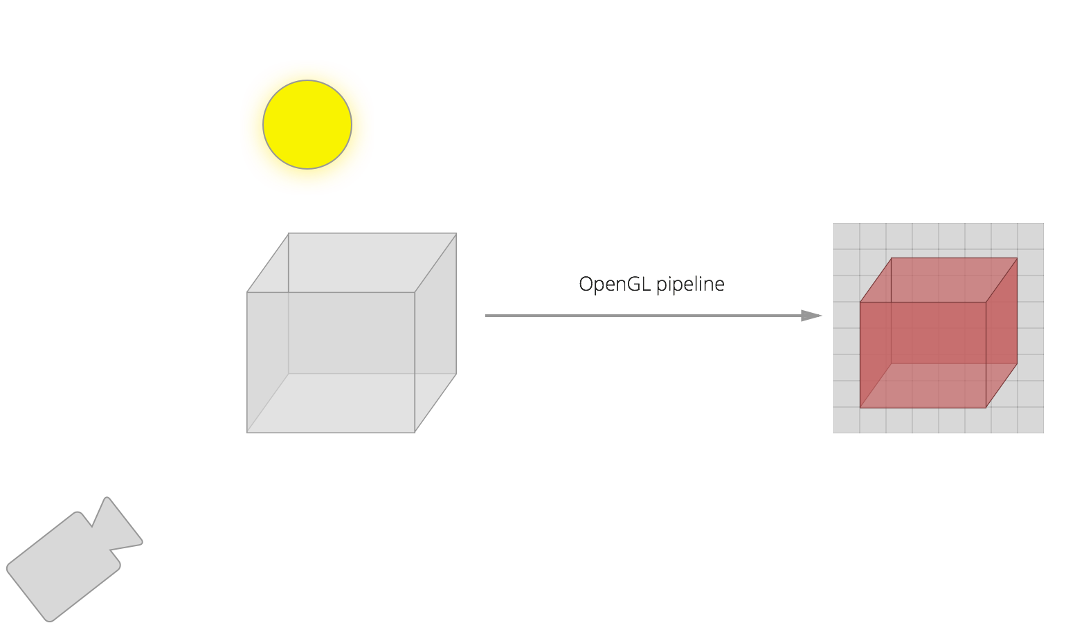
In the original OpenGL model, we would define the state of the program (light source, vertices, colours, and camera position, amongst others). Then, we would send it to OpenGL, which would run with that state, and output an image.
Fairly simple, but lacking power.
1.2.2. The new model
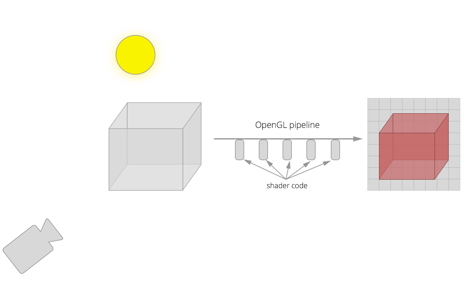
In the new model, the pipeline not only runs with the state defined before running it, but also we can give OpenGL shader code that will run at various stages of the pipeline.
For example, we can tell OpenGL some transformations to do to every vertex of our shape. We can also tell OpenGL some transformations to do to every pixel of our shape (for example, very useful to apply lighting effects).
The output is also an image.
1.2.3. The pipeline itself
The figure below shows what happens in the pipeline (we can write shaders for each of the steps).
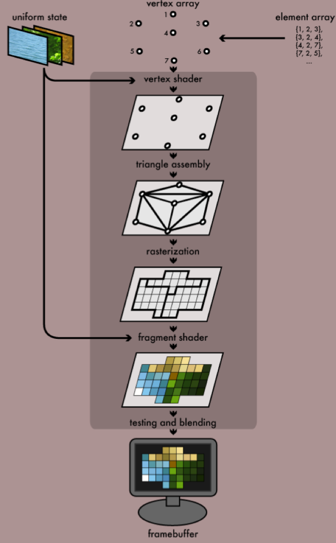
(see http://duriansoftware.com/joe/An-intro-to-modern-OpenGL.-Chapter-1:-The-Graphics-Pipeline.html)
1.2.3.1. In more detail
The figure below shows the different shaders and the pipeline itself in more detail.
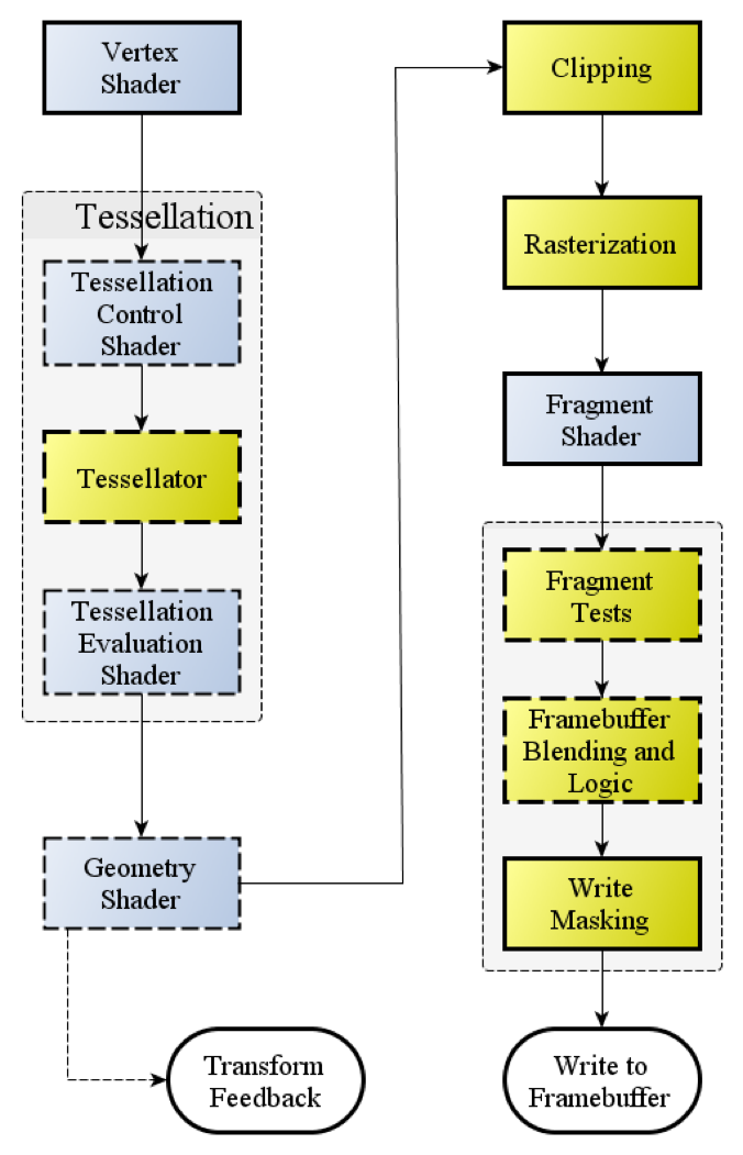
(see http://www.opengl.org/wiki_132/images/RenderingPipeline.png)
The blue boxes are where we can write shaders and pass them to the OpenGL pipeline. The yello boxes are the ones we cannot change, but happen in the pipeline.
1.2.4. Graphics journey
So we start with a number of vertices (in a vertex buffer) and related data (like textures: images we apply on to the planes that make up the shapes to make them look like things, such as rocks or trees).
We also have a vertex shader. At minimum, this calculates the projected position of the vertex in screen space. But it can also do other things, like generate colour or texture coordinates. The vertex shader runs for every vertex that we pass through the pipeline.
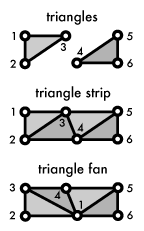
Then comes primitive assembly, where we create triangles from vertices. Here we can use a number of ways of assembling, such as GL_TRIANGLE_STRIP or GL_TRIANGLE_FAN (see below).
Then we rasterize, where we output pixel fragments for each triangle.
Finally, the fragment shader can process the pixel fragments and do things with them, like output colour and depth values. The output of this gets drawn to a framebuffer. Then we can put this in a window or used in other ways. The fragment shader runs for every pixel fragment!
So this is what happens (gif)
1.2.4.1. Vertex shader
One matrix is used for each transformation. This is each of rotating, translating, or defining views and projections (they are essentially moving the model to make it look like we are looking at it from a specific angle).
Imagine we want to translate (move) and rotate our model. We could define this with two matrices, and then we could pass these two matrices to the vertex shader, to apply them to each vertex in the model.
However, this would mean that the shader would have to calculate the final transform (translate + rotate) for each vertex. It would be more optimal to calculate the final transform in our application, and then pass that transform–in the form of a matrix–to the shader. That way it only runs once (albeit in the slower CPU, rather than the GPU).
We would also pass our shaders the projection and view matrices, although we could also combine these in the application. I find it more readable to not combine them, and so I end up with projection, view, and model transformation matrices.
A simple shader to execute the transforms would look like this:
attribute vec4 position;
uniform mat4 model, projection, view;

void main()
{
    gl_Position = projection * view * model * position;
}
The variable gl_Position is a standard name variable which is the position of the vertex at the end of the transformation, before it is passed through to the next step of the pipeline.
1.2.4.2. Optional shaders
After the vertex shaders come the optional tessellation and geometry shaders.
Tessellation shaders can add extra detail to patches of polygons.
Geometry shaders can modify, add, or remove vertices.
1.2.4.3. Primitive assembly
Afterwards the pipeline assembles the shapes using primitives. For example, a rectangle may be assembled using GL_TRIANGLES as two triangles. It may be assembled using GL_POINTS as four points, one on each vertex.
1.2.4.4. Clipping
Clipping is the act of discarding vertices that are outside the viewing area, so as to decrease load trying to draw things that aren’t going to be visible.
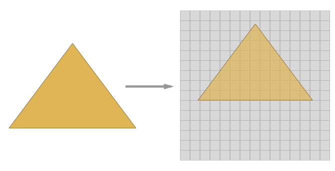
1.2.4.5. Rasterization
Here the pipeline samples at the pixel level, producing pixel fragments where shapes don’t occupy a full pixel. For example, if the edge of a rectangle cuts through a pixel.
1.2.4.6. Fragment shader
These shaders run for each pixel fragment that has been through the pipeline. It obtains colour and depth as interpolated values from the vertex shader.
A simple fragment shader which would just assign the interpolated colour would look something like this:
varying vec4 v_color;
void main()
{
    gl_FragColor = v_color;
}
Once again the variable gl_FragColor is a standard variable name that should be used as output of the fragment shader.